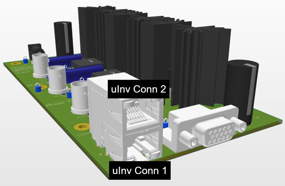
uInverter Board Connections
This document describes the connections on the uInverter board.
For detailed review of the board, please refer to the schematics in the AMDC-Hardware repo.
Connections with the AMDC
PWM
The PWM connector on the uInverter board uses DB15 connector, similar to the Drive Outputs connector on the AMDC.
Three-phase PWM signals A+, B+, C+ generated on the AMDC are carried over to the uInverter on this connector CONN2 - PWM.
Pin # |
uInverter |
AMDC |
|---|---|---|
1 |
|
|
2 |
|
|
3 |
|
|
4 |
|
|
5 |
|
|
6 |
|
|
7 |
|
|
8 |
|
|
9 |
|
|
10 |
|
|
11 |
|
|
12 |
|
|
13 |
|
|
14 |
|
|
15 |
|
|
Analog
For providing feedback of current and voltage (analog sensing), the uInverter board uses the RJSAE connector similar to the analog connector on the AMDC.
Three phase current signals and the DC link voltage signal generated on the uInverter are fed back to the AMDC using connector CONN3 - ANALOG SENSING.

Pin Number |
|
|
|
|
|---|---|---|---|---|
1 |
|
|
|
|
2 |
|
|
|
|
3 |
|
+15V |
|
+15V |
4 |
|
|
|
|
5 |
|
-15V |
|
-15V |
6 |
|
|
|
|
7 |
|
|
|
|
8 |
|
|
|
|
External Connections
DC Voltage Connector
The 12V DC supply uses a barrel jack connector with ground-center as marked on the PCB. Here is the link to the datasheet of the connector.
Here is an example of a usable 12V wall-wart connector.
A phoenix connector J7 is also provided for an alternative 12V supply connection.
Jumper connection
The phase connection Phoenix connectors are normal-closed (NC) connections.
Hence, jumpers should be used to short ONLY the following connectors - J1, J2, J3, J4, J5 and J6.
Here is a link to an example phoenix contact jumper.
For more details, please refer to the schematics.