Tutorial: Blink
Goal: Run the baseline firmware on the AMDC hardware.
Complexity: 1 / 5
Estimated Time: 20 min
This tutorial goes over:
Building the baseline firmware and programming the AMDC hardware
Communicating to the AMDC via UART and the command interface
Changing AMDC state via commands
Tutorial Requirements
Working AMDC hardware
Completion of the “Meet the AMDC” tutorial
Access to Xilinx tools for building firmware
Step 1: Building baseline firmware and programming the AMDC hardware
The first step is building baseline firmware for the AMDC.
The default code provided in the AMDC-Firmware GitHub repository will be used for this.
This tutorial will not modify any code: only build, compile, and load it.
Building the complete firmware stack for the AMDC is fairly involved. Since it is a common task, a dedicated self-contained document is provided: follow the steps in this document.
After completing the steps in the linked document, the AMDC should be running the compiled code, and the RGB LEDs should be blinking continuously. If the LEDs are not on, do not proceed; debug until they start blinking!
Step 2: Communicating to the AMDC via UART and the command interface
Now that the firmware is running, you need to connect to the AMDC via the command interface. The command interface allows users to interact with the AMDC by running commands to get/set system state. The interface is similar to a typical command-line interface (CLI) on a shell program on e.g. Windows, Linux, Mac, etc.
To complete this step, plug in a USB cable to the AMDC and confirm the AMDC appears in the device list on your host computer.
For REV D hardware, you will need the Silicon Labs drivers for the UART interface to appear as a COM port. For REV E and beyond, the UART serial driver is typically included in the host OS due to a different circuit design.
Terminal Software
The minimal host software required to use the AMDC is a simple serial terminal. There are a few options:
Option 1: Xilinx SDK built-in terminal
The SDK provides a terminal via the SDK Terminal pane:
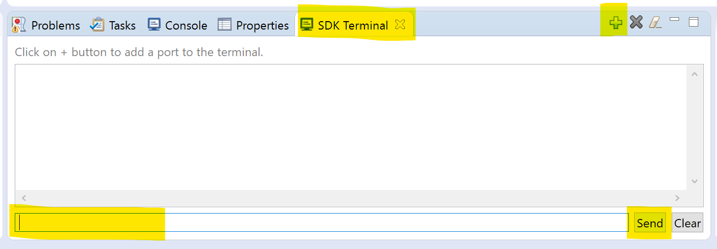
To use this, you’ll need to click the + button to set up a new connection.
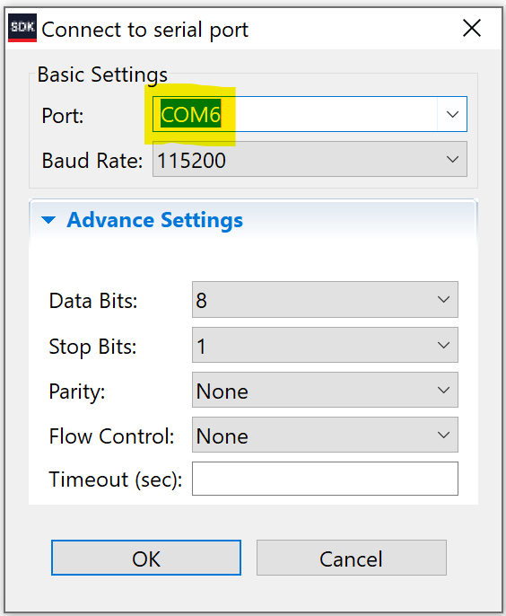
The settings should match the following screenshot, but you must select the correct port for your AMDC. Find the port using the “Device Manager” software on your computer.
Option 2: Tera Term
Tera Term is a stand-alone terminal program which can interface with the AMDC. Sometimes it is preferrable to have the serial UART interface not tied to the SDK so that it operates regardless of SDK status.
Download TeraTerm from their website: https://ttssh2.osdn.jp/index.html.en
Option 3:
There are many other terminal options available. For example:
Pick one that you are comfortable with and use it.
Step 3: Changing AMDC state via commands
Now that the AMDC is hooked up and the code is running, it is time to send some commands to interact with the AMDC.
Commands are sent by:
Typing the ASCII letters via your keyboard into the terminal software
Pressing
[ENTER]to run the command
All commands should be terminated by an ASCII new-line character, \n, which is usually sent by the host terminal software automatically via pressing [ENTER].
help Command
The AMDC will provide a list of the available commands and a short description of what they are via the help command.
Type help followed by [ENTER] to send the command.
The AMDC should output a list of commands with the help text appended.
Notice that each base command has associated sub commands or arguments/parameters.
blink command
By default, the baseline code contains a command called blink.
From the help output, it is seen that blink accepts the following sub-commands:
hello <name>- Print hello to screeninit- Start taskdeinit- Stop taskstats print- Print statsstats reset- Reset stats
Try typing blink hello bob and observe the response.
Now, try typing blink hello nathan; notice the response is different.
Type blink hello fred; again, notice a different response.
To understand the differences in responses from the AMDC, explore the AMDC-Firmware code base to find the blink command handler function.
Now, try typing blink deinit. The RGB LEDs stopped blinking!
Turn them back on by typing blink init.
The init and deinit sub-commands are used here to start and stop the blink system task, which is responsible for updating the RGB LED state.
Try out the stats sub-commands. Notice that the output is always zero.
By default, the code does not enable task timing statistic measurment.
A future tutorial will go over profiling code executation time.
Conclusion
Congratulations! You now understand how to build and run AMDC firmware, and interact with it via the command interface.