μInverter
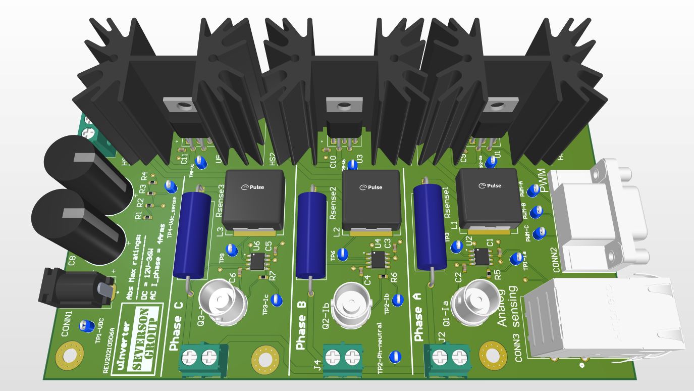
The μInverter (micro-inverter) board is an accessory for the AMDC. The purpose of this board is to serve as a low-cost, micro-level prototype board to demonstrate three-phase current regulation using the AMDC. It uses a 12V DC supply to drive a three phase RL load circuit to emulate a motor.
Features
Three phase AC current and DC bus voltage sensing feedback to AMDC.
Test points to measure voltages at various locations in the supply as well as load circuits.
BNC connector to directly measure the current waveforms on an oscilloscope conveniently.
Specifications
Metric |
Symbol |
Value |
|---|---|---|
Switching Device |
IXYS IXDN614YI |
|
Current Sensing |
Shunt + TI INA143 |
|
DC Capacitance |
\(C_\text{dc}\) |
1000 μF |
DC Voltage |
\(V_\text{dc}\) |
5 to 35 V |
Phase Current(rms) |
\(I_\text{ph}\) |
0 to 4 A |
Switching Frequency |
\(F_\text{sw}\) |
0 to 1 MHz |
Effective Load Parameters |
\(R\), \(L\) |
650 mΩ, 120 μH |
The phase current and switching frequency are limited by the switching device thermal dissipation.
The resistance \(R\) is given at \(V_\text{dc} = 12~\text{V}\).