Flashing AMDC
During development, JTAG will be the primary interface for programming and debugging the AMDC firmware. Once code is stable, an image can be programed into the AMDC non-volatile memory (NVM). This allows board to boot itself when powered up.
The following steps outline how to create a boot image and flash the AMDC NVM.
This process varies slightly between single core, and dual core projects. Differences will be noted in the appropriate steps.
Going through this process for the first time, the “create boot image” dialogs may differ slightly from the ones shown below. Use good judgement here and it should be evident what the appropriate steps are. Once you have created an initial boot image - even if it is incorrect and needs to be fixed, you can then match the dialogs exactly to the ones shown below.
Generating boot image file
The PicoZed system-on-module (SoM) on AMDC includes a flash memory device which stores the boot image for start-up. We need to first generate the appropriate image which will be loaded into this memory. This process is the same for both single core, and dual core projects.
Ensure you have fsbl project in SDK
Xilinx provides a First-Stage Bootloader application project which we will use to create our boot image. If you do not have the fsbl project in SDK:
File>New>Application ProjectName it
fsblEnsure
Board Support Package:isUse existing: amdc_bspClick
Next >Select
Zynq FSBLtemplateClick
FinishYour new
fsblproject will be imported and build. It should not have issues.
Generate boot image
Right click on the
fsblproject directory in SDKSelect
Create Boot Image

Ensure popup menu settings look like the following.
Explaination of settings: .MCS is the file format which is supported for QSPI flashing. The list of three items for “Boot image partitions” must always be the following in this order: fsbl.elf, FPGA bitstream .bit file, your user *.elf file.
Skip below for dual core project procedure.

Attention
For dual core projects, there will be multiple .elf files. The order is important!
Navigate to your
$REPO_ROOT\AMDC-Firmware\sdk\app_cpu0\Debugfolder and locate the fileapp_cpu0.elf.Add this to the Boot Image Partitions area
Navigate to your
app_cpu1location, usually this is located in the$REPO_ROOT\AMDC-Private\Debugfolder.Add the .elf file to your Boot Image Partitions after the
app_cpu0.elffile.
Click
Create ImageIf it warns that another file already exists, click
OKIt will take a second to create the boot image
Programming the flash memory device
After generating the boot image *.MCSfile, we need to program the flash device for persistent storage.
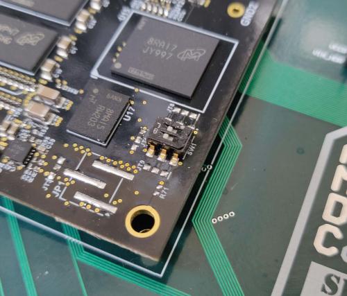
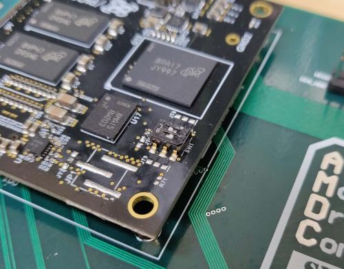
Ensure you powered up the board in the correct boot mode. This is selected via the switches on the PicoZed PCB. See image below for switch positions for JTAG mode (what you want).

Click
Xilinx Toolsfrom the main dropdown in the SDKClick
Program Flash

Ensure popup window looks like the following:
Click
ProgramIt will start flashing the board. This will take ~3 minutes…
Known Issues
Sometimes, when you try to flash the device (i.e. set 5-6 above), the fsbl main function will appear in SDK because a breakpoint is reached. This occurs because the SDK debugger is still attached to the AMDC. To fix this, disconnect the processor from the SDK Hardware Manager window.
Configure PicoZed to boot from flash
Now the boot image has been loaded onto the PicoZed flash device. We need to configure PicoZed to use it when booting.
Set PicoZed switch positions to the flash boot mode (see image below).

Test
AMDC should now be programed and ready to go! Time to test.
Power cycle the board.
Ensure that
FPGA DONEyellow LED comes on after ~1 second of powering up, and your loaded code is running.
Attention
If you see the FPGA DONE LED turn on, but your program appears to not be running, check the order of the boot partition with the above steps.
Notes
NOTE: you will need to put the PicoZed switches back to JTAG mode if you would like to continue development using JTAG.