Analog Encoder Interface Board
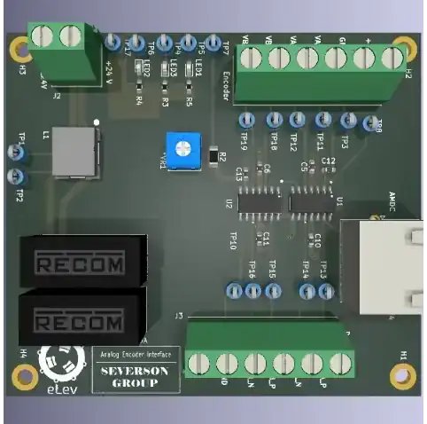
This file outlines the use of the Analog Encoder Interface Board. The Analog Encoder Interface Board is intended to amplify signals from an analog encoder (sin/cos outputs) to be able to measure rotor position with using the analog input ports of the AMDC.
Relevant Hardware Versions
AMDC Rev E and newer.
Revision History
See the changelog.
Design Requirements and Considerations
Input Signals (From Analog Encoder)
This board design is designed to be compatible with the RLS RM44 Rotary Magnetic Encoder:
Differential sin/cos signals
Amplitude: 0.25V
Offset: 1.6V
Output Signals (To AMDC)
The goal of the board is to condition the input signals to quantities that are easily measured by the AMDC’s analog interface. The output signals should meet the following specification:
Differential sin/cos
No DC offset
Reside within +/- 10V range
Block Diagram
The following block diagram illustrates how this board conditions sin/cos position signals for use by the AMDC:
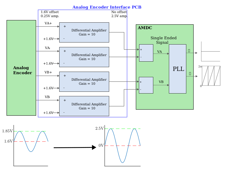
The blue box shows the functionality of the Analog Encoder Interface Board. It removes the DC offset of each signal in the differential pair of encoder outputs and amplifies each signal by a gain of 10.
The green AMDC box illustrates example functionality that can be implemented in the AMDC to use the resulting signals to calculate shaft speed and position.
External Connectors
There are 4 connectors on the boards. The details of the pinout are provided below.
6 pin connector J1: Encoder
Pin number |
Signal name |
|---|---|
1 |
5 V |
2 |
GND |
3 |
VA_P |
4 |
VA_N |
5 |
VB_P |
6 |
VB_N |
2 pin connector J2: Power supply
Pin number |
Signal name |
|---|---|
1 |
24 V |
2 |
GND_24V |
6 pin connector J3: Drive
Pin number |
Signal name |
|---|---|
1 |
NC |
2 |
GND |
3 |
VB_N_OUT |
4 |
VB_P_OUT |
5 |
VA_N_OUT |
6 |
VA_P_OUT |
Ethernet connector J4: Board-to-AMDC
Pin number |
Signal name |
|---|---|
1 |
VA_P_OUT |
2 |
VA_N_OUT |
3 |
NC |
4 |
GND |
5 |
NC |
6 |
GND |
7 |
VB_P_OUT |
8 |
VB_N_OUT |